


Tobias Jung, Zoltán Kiss- Area Sales Manager - East Europe - Endrich GmbH.
Parameters of current–sensing resistors
9 February 2018

Summary :
In order to measure the current in an electric circuit, precisely kept low resistance current sensing chip resistors should be used and the voltage drop over the component is measured. The required characteristics are tight initial tolerance, small TCR, high nominal power and small size. There are however other important factors, like the affect of self heating, the material of the resistive element and on high frequencies the equivalent series inductance (ESL) to take in account. In this article we will discuss these factors and their role to be able to make a precise current measurement with SUSUMU’s unique KRL series of shunt resistors.
Low resistance current sensing chip resistors have been introduced originally as over-current protection devices in power supply circuits. Their application range has been extended and these components become important components for power management of electronic devices and used to measure or adjust current. When an engineer wants to compare different current sensing resistors’ resistance stability over temperature, TCR alone would not give precise information about the measurement accuracy due to the fact resistance is also influenced by the self-heating of the components. First thing to take in consideration when designing-in a component to the application is the datasheet provided by the manufacturer. It is recommended however to validate the included data in real application or laboratory conditions. In case of chip resistors - besides the usual parameters like the resistance, the nominal power and the initial tolerance of resistance at room temperature - the TCR (Temperature Coefficient of Resistance) as an indication of how the resistance changes with the temperature should be also considered.
Low resistance current sensing chip resistors have been introduced originally as over-current protection devices in power supply circuits. Their application range has been extended and these components become important components for power management of electronic devices and used to measure or adjust current. When an engineer wants to compare different current sensing resistors’ resistance stability over temperature, TCR alone would not give precise information about the measurement accuracy due to the fact resistance is also influenced by the self-heating of the components. First thing to take in consideration when designing-in a component to the application is the datasheet provided by the manufacturer. It is recommended however to validate the included data in real application or laboratory conditions. In case of chip resistors - besides the usual parameters like the resistance, the nominal power and the initial tolerance of resistance at room temperature - the TCR (Temperature Coefficient of Resistance) as an indication of how the resistance changes with the temperature should be also considered.
Selfheating of current sensing resistors

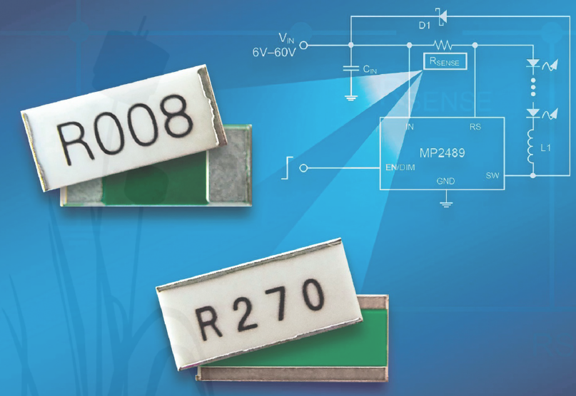
Current sensing (shunt) resistors (see cover picture) are subject to power loss calculated by
P = I2R
derived from Ohm’s law. Therefore, to keep the dissipated heat low in order to avoid self heating and its affect of the resistance itself, the device manufacturers offer the range of available resistance values down to the milli- and even the micro-ohm region. However, in order to cope with the everincreasing currents to be measured, they must also adapt the performance specifications of the components. This is done using various technologies, such as in the construction as multi-layer resistance, with foil or curved solid metal as a resistance element.
TCR and PCR
As written earlier, when comparing different current measuring resistors, the TCR alone would not give sufficient information about the expected accuracy over the operating temperature range, because the resistance would not only change with the ambient temperature, but also due to self-heating. Thus, another parameter comes into play: the PCR (Power Coefficient of Resistance). An inferior in terms of TCR device can deliver more accurate reading than its competitor - due to the PCR effect- if its self-heating is significantly lower. An example: Basically it can be assumed that the resistance of type B in "Table A" would show more accurate results due to its narrower TCR. Assuming R=1 00 mr for both types, the self-heating, depending on the structure or technology used, shows very much different values. In this example, the type B with a TCR of ± 40 ppm is heated by 1 00 K, while the metal foil resistor of the KRL series with TCR of ± 50 ppm would only warm up by 60 K (see table).
Comparison of resistance change of different shunt technologies:
| Type | Technology | TCR[ppm] | Self heating ∆T [°K] | Nominal resistance R0 [mΩ] | Real resistance R [mΩ] |
|---|---|---|---|---|---|
| KRL | Metal foil under ceramic substrate | +/- 50 | 60 | 100 | 100.3 |
| „B” | Bended metal shunt | +/- 40 | 100 | 100 | 100.4 |
The self-heating resistance is calculated according to R = R0 TCR ∆T
100.4 mΩ for the type B respectively 100.3 mΩ for the type KRL.
One can see from this calculation example that due to lower self-heating the KRL series current sensing resistor - despite its larger temperature coefficient - provides the more accurate measurement result.
Power derating
Depending on the technological and material-specific possibilities, these resistors are specified differently. The maximum nominal power of a component is usually determined by its thermal limitations. For this purpose, the temperature is measured, for example, at the top of the chip and / or at its contacts. When the limit temperature is reached, a derating in the power dissipation capabilities starts. The maximum power loss for which a given resistance value can be kept therefore heavily depends on the heat dissipation ability of the components. To avoid power derating the manufacturers strive to avoid so-called hotspots in the design of the resistors. The power rating of the resistor shows what is the maximum energy that the resistor is able to dissipate without being damaged or degraded. Most of the manufacturers indicate their power rating at 70 °C in free airflow, above this temperature there is a degradation due to stress on the material. The temperature where the power dissipation must be derated to 0 is also indicated, this is the maximum possible storage temperature of the resistor.

Incase of SUSUMU KRL series, depending the constantan or manganin alloy used as the material of the resistive element, the power derating curve shows higher derating point, it’s due to the unique construction of the component. This is the reason, that usually the KRL series could be used till higher rated power or on the same rated power in smaller case size than many other parts.

Currentmeasurement in practice
This reliable method of measuring currents can be found in automotive applications, but also established for example in home appliance technology. One can find such current sensing resistors in the vehicle in the trunk lid control or seat adjustment; also valve regulators or brake systems require a precise current measurement. A manufacturer of cleaning robots, such as those used in residential places, was able to solve three problems at once using the KRL resistors. The DC / DC converter of the robot’s power supply requires a 10 mΩ shunt, which is specified for a power loss of at least 2 W, as currents above 10 A should be measured, and the controller requires input voltage of at least 100 mV. Usually for 2W heat dissipation a shunt with 2512 size is required, but due to limited space it does not fit. By choosing resistor with soldering terminals on its long sides (long-side terminal KRL), a smaller 201 0 case size is enough, as on wider solders the heat is conducted easier and faster towards the PCB.
Material of resistive element
As current sensing is based on voltage measurement on a precisely stabile resistance, all factors that may have influence of this voltage have to be considered. Above we detailed the TCR’s and the PCR’s influence, but there is a further effect that may lead to measurement mistakes. As the resistor consists of different metal materials connected together, the so called thermocouple-effect (Seebeck-effect) may also distort our measuring. When different metals are connected together at one point, and this intermetallic junction is subjected to heat, a small (microvolt magnitude) voltage may arise between the free ends, which lead to further distortion of the precise measurement. Constantan based resistive elements have higher thermo- EMF, while the manganin versions are considered to be low thermal EMF sources, therefore more stabile for precise applications.
ALCÍM
There is an important factor to take in account for making precise current sensing on high frequencies, the equivalent series inductance (ESL) of the resistor, which should be kept as low as possible.
Numbers of electronic devices require precise power management, which could be provided by using DC/DC converters. These switching devices operate on several hundred kHz frequencies. If the ESL of the current sensing resistor is large, the transition switching pulses contain noise, which affects the accuracy of the control, as the inductive impedance is proportional to the frequency and the inductivity:
Z ~ 2 π f ESL
However, if ESL is small, such noise will become insignificant.
The inductance of conductor (non-coil) is provided by the following equation:
L=0.002 h(2.303log104h/d-1+μ/4)
Where
h: conductor length,
d: conductor width,
μ: permeability
The inductance increases with permeability of the material and length of the conductor and decreases with the width of the conductor. Therefore, when the material is fixed, low ESL can be obtained by shortening the conductor length and widening the conductor width. Susumu’s long-side terminal type resistor realizes low ESL with shorter length and wider width of the resistive element by using its longer side as the terminal. The following measuring result shows the shape of the transition switching pulses using a short-side terminal resistor and a long-side terminal resistor, demonstrating a clear reduction of the switching noise. Using such low ESL current sensing resistors, the designer can avoid the need of using additional noise reduction circuits.
Long side terminals – better heat performance, better noise reduction
Susumu’s long-side terminal low resistance chip resistors were developed to increase heat dissipation. Due to this high power capability, these chip resistors have been very popular. In addition, new demand has arisen for high frequency applications, where the low ESL of the long side terminal versions also provided significant advantages. Noise suppression in combination with low parasitic inductive influence indicate the accuracy increase significantly. In the charge controller of electrical devices, near the battery, thermal properties play an important role as the electronics and battery heat up during charging and discharging. Due to the inverted structure (carrier ceramic above, resistive element below) are in the resistor, no hotspots are formed, and this is rapidly cooled, which reduces the influence of TCR / PCR on the measurement result.

KRL series of SUSUMU
The KRL resistor series of Susumu (distribution: Endrich Bauelemente) are designed for high nominal power with low nominal resistances and thus for use in current measurement. The structure with metal foil, which is attached to the underside of a carrier ceramic, promotes the uniform cooling of the component (Figure 1 ). Further characteristics of the KRL series are low noise, low parasitic inductances, low thermal EMF, which could falsify the measurement result, low dead weight and their robustness. The latter is due to the inverse structure - with the metal foil under the carrier ceramic. The organic adhesive layer absorbs mechanical stresses due to the different length expansion of ceramic and printed circuit board material. The components can thus clearly exceed the requirements of the automotive standard AEC-Q200 up to the largest case sizes. The KRL series is available in different layouts: with rated resistances from 1 mΩ to 1 Ω , in sizes of 0603 to 4320, in rated power classes from 0.25 to 1 0 W, as standard with a TCR of 50 ppm, with initial resistance tolerances of ± 1% and with short-side, long-side, 4K and gold terminals.
Literature: [Tobias Jung - TCR- und PCR-Effekt in Strommesswiderständen - Kühl kalkuliert] http: //www.elektronik-informationen.de/59057
| Share on Facebook | Share on LinkedIn |
References
This article has been published on the following locations:
| # | Media | Link |
|---|---|---|
| 1 | Elektronet 2018/1 | Elektronet : elektronikai informatikai szakfolyóirat, 2018. (27. évf) 1. sz. 27-30. old. |
| 2 | Hungarian version | Áramérzékelő ellenállások technikai paraméterei |
| 3 | TechStory M2M | Áramérzékelő ellenállások technikai paraméterei |
| 4 | Jövő Gyára 2018/1 | 2018. 1. sz. 11-14.o. |
| 5 | Bodo's Power Systems 2018 August | Parameters of Current-Sensing Resistors |