


Zoltán Kiss- Area Sales Manager - East Europe - Endrich GmbH.
Over voltage protection with TVS devices
16 May 2014

Summary :
When the voltage of the input of an electric circuit or element raises above the level it is maximum rated at, it may be overstressing it depending on the overvoltage event’s duration, which can be a transient spike, or a permanent surge. These overvoltage events may be resulted by natural sources like lighting or human origin, like electrostatic discharge, switching of high inductive loads or operating circuits generating electromagnetic interference. Effective protection against overvoltage is essential task next to the functional design. Avalanche Breakdown Diodes (Transient Voltage Suppressor Diodes) from Protek Devices offer a great flexibility in circuit over-voltage protection, as available from 2.8V to 400 Volts, and power rating of from 80 Watts to 30 kWatts.
Overvoltage events
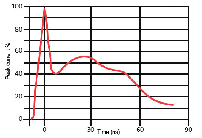
Voltage transients can be categorized into three types : ESD, Surge and Load dump. Electrostatic discharge (ESD) occurs, when a charge is exchanged between two objects of different charge potential, mainly between human beings and metal objects. Usually a visible spark is generated as a result of breaking down the isolating dielectric between the objects. This is featured by 2-15 kV (level 1-4) air discharge voltage, relative small energy and short (ns) duration.
The surge is a different kind of transient overvoltage event, that is characterized by longer (microsecond) duration, large energy. A surge voltage is caused by a switching transient or lightning strike.
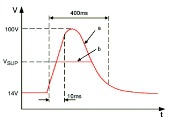
Load dump is a long duration , usually millisecond long overvoltage event, usually caused by switching off a load from an inductive supply, like battery is disconnected from charging circuit, while charging. The millisecond long rise is followed by a slow decay, resulting a high energy transient.
Transient Voltage Suppressors
Silicon Avalanche Junction TVS (transient voltage suppressor) devices contain a P/N junction similar to a Zener diode, having however a lager cross section, proportional to the surge power handling rating of the device. In order to handle longer duration transients, engineers can choose higher sizes with better heat dissipation. The devices are available from chip size to large module units. Although rated at lower surge current levels than MOVs, the voltage as well as the power capabilities can be increased by using more devices series or parallel. TVS diodes can handle today high surge currents, for example Protek’s 2700SM78CA can handle 18 kA, a 12V rated 600W device has a 8/20 s surge capacity of 140 A. Failure mechanism of TVS diode is a short circuit. They have fast response time as a result of the silicone technology, because the response s proportional to the electron’s speed. As the protection device should be invisible at normal operating conditions even on higher frequencies, sometimes ultra low capacitance has to be achieved (pF). GBLC08CLC has a line capacitance of 0.4 pF. TVS devices can be used in unidirectional configurations for DC lines as well as in bidirectional organization for AC applications. Unlike MOVs, which display initially perfect leakage behavior, but later performance degrades with every surge exposure, TVS has no aging effect, the leakage current characteristic shows no degradation over time. It has a response time in the sub nanosecond range as well as low clamping factor (~1.33).
Protection solutions for lightning transients
Lightning is the most severe threat for outdoor electronics, having typically 20 kA peak current and producing intense electric and magnetic fields, which couple into neighboring power lines, data lines causing damage to equipments. Usually a two stage protection consisting of a crowbar primary and a clamping secondary protection can provide sufficient solution. On the primary side usually damping resistors (R1,R2) are used for limiting the current and GDT devices or Thyristor Surge Suppressors as common mode protection are used to shunt this to the ground.
In order to meet the requirements of the concerning standards, the primary protection has to withstand over voltages, that exceed 5 kV and surge currents up to 250 A for TSS and 10-20 kA for GDT.
Near the indoor equipment a secondary protection level has to be applied to suppress the remaining lighting or switching transients. At this point TVS devices are used to divert the transient current , clamp the voltage and save the protected equipment. The fast response and the low clamping voltage of the TVS compensates for the high firing voltage of the GDTs. According to norms and standards, the secondary protection has to withstand over voltages that exceed 1500V and surge currents up to 100A (8/20 µs, 10/1000 µs and 10/700 µs surge waveforms).
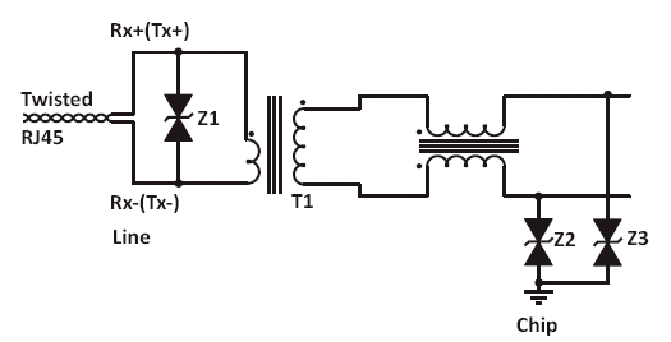
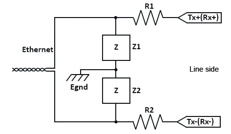
As figure shows protection is imposed on both sides of the Ethernet magnetic transformer. On the line side of the isolation transformer a low capacitance TVS (Z1) provides voltage and current limiting to differential mode surges. On the chip side two TVS devices are shunted to ground in order to protect the IC from the transient energy, that is coupled through the transformer. Another solution is to use steering diodes on the chip side, which are low in junction capacitance, therefore reduce insertion loss of signals on high speed data lines.
Protection solutions for ESD
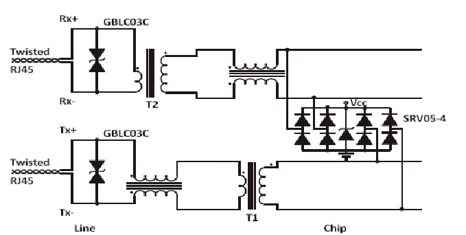
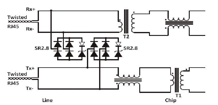
Electrostatic discharge is a single , fast, high voltage and high current event. For low speed I/O or power supply applications flp chip devices are recommended due to their small size and low cost. For high speed applications low capacitance devices are essential ( SR2.8, SVLU2.8-4, GBLCxxC and SRV05-4). A TVS/Steering diode combination can also be used in order to suppress the line-line ESD transients.
Paralleling TVS devices for higher power capability
Protek’s TVS diodes are available in voltage ranging from 2.8V to 400V and in power ratings from 80W to 30 kW. These devices however are successfully usable in higher voltage and power combinations by organizing them in serial or in parallel. The power rating is expressed based on an industry standard pulse waveform ( e.g. 10/1000 µs) , which has a 10µs rise time and an exponential decay to half of its peak at 1000 µs. For those applications in which the transient power exceeds the limits, it is possible to configure more TVS in parallel organization, which will provide the same voltage response as a singe unit, but the current handling capability has been increased. It is important, that the individual diodes are matched in terms of clamping voltage in order to equally share the transient current.
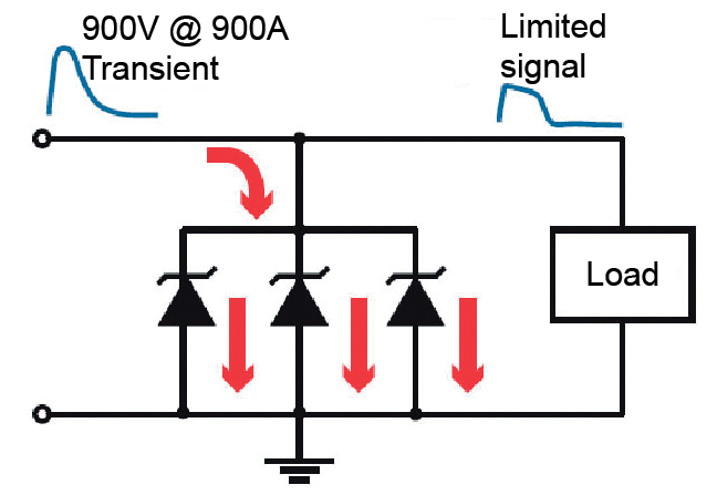
Even if the three TVS diodes have the same part number, their breakdown voltage, reverse leakage current and clamping voltage are individual values, therefore matching should be applied by means of applying selections.
Peak pulse power (Ppp)
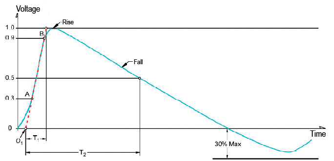
TVS devices are categorized by their maximum peak pulse power rating for a specific pulse wave shape. The power rating is indicated as a curve representing a derating of power (Ppp) over a given pulse duration (td).
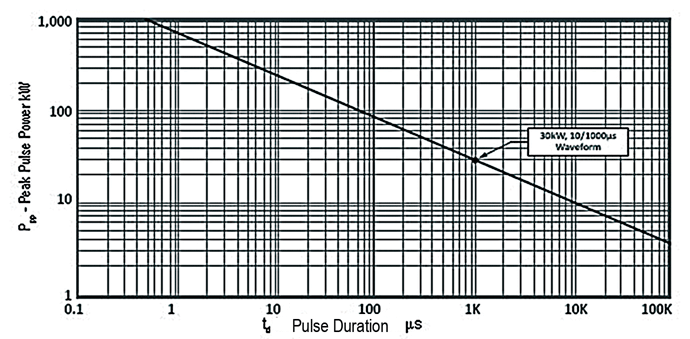
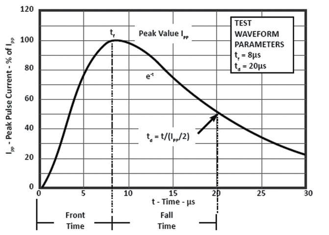
The pulse duration is defined as the front time plus fall time, where front time is the length of time needed to reach the peak value, and fall time is characterized by the required time to the pulse to fall to the 50% of the peak vaue.
The maximum peak pulse power is equal to the maximum clamping voltage multiplied by the maximum peak pulse current. The max clamping voltage is considered constant, independent from time representing the threshold voltage of the P/N junction of the diode. Therefore the power curve represents the current rating over time.
The easiest way of calculating the Ipp at a given pulse duration is if we divide the peak pulse power rating (Ppp) by the maximum clamping voltage.
| Share on Facebook | Share on LinkedIn |
References
This article has been published on the following locations:
| # | Media | Link |
|---|---|---|
| 1 | Elektronet 2014/4 | Elektronet : elektronikai informatikai szakfolyóirat, 2014. (23. évf.) 4. sz. 25-27. old. |
| 2 | Elektronet online | Túlfeszültség-védelem TVS eszközökkel |
| 3 | Hungarian version | Túlfeszültség-védelem TVS eszközökkel |
| 4 | Tech Story M2M | Túlfeszültség elleni védelem TVS diódával |