


Zoltán Kiss- Area Sales Manager - East Europe - Endrich GmbH.
Ripple cancellation with low ESR polymer capacitors
7 December 2015

Summary :
To produce different voltage levels out of the battery voltage could be done on several ways, like using resistor based voltage dividers, or linear regulators, but these solutions can only provide lower level of voltages and the efficiency is low, as − if the voltage drop is high and the current is large − , the excess power will be lost by dissipating remarkable heat. Better to use today switching mode DC/DC converters, which temporarily storing energy in magnetic or electric storage components and releasing this energy to result different voltage level on the output. The efficiency will be remarkable higher resulting better battery lifetime at the end. The high frequency swithching however causes voltage ripple on the output, that has to be minimized in order to avoid mailfunctioning of the supplied device. Most obvious solution is to use a fiter capactor for smoothing ripple voltage on output, which is possible by using e.g. polymer capacitors.
Operation principle of DC/DC converters, reasons ripple voltage generation
Those switching more DC/DC converters, that are characterized by lower Vout than Vin are generally called step down or buck converters. Their working principle is based on the ideal circuit shown on figure below:
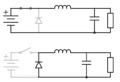
The switch on the circuit represents the element that is used for connecting and disconnecting the circuit and the battery, which is in reality a MOSFET or an IGBT component. The inductor is used for storing the energy, by building up its magnetic field right after the battery is connected to the circuit. During charging, the inductor would produce a voltage drop that is reducing the voltage of the load. If the switch opens before the charging is complete, the output voltage remains always less than the battery voltage. At this moment the flyback diode switches on, and provides a closed circuit, which could then discharge the energy stored in the magnetic field. As long as the switch off period is shorter than the discharge time of the inductor, the voltage of the load is always higher than zero, as the inductor pumps energy and supports current flowing through the load. The average voltage on the output is always lower than the input supply voltage.
Those switching more DC/DC converters, that are characterized by higher output voltage than supply voltage are called step up or boost converters. The ideal circuit diagram presents the working principle:
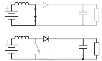
When the switch is “on”, the inductor starts to charge, while load voltage is zero. Once the switch is open the energy stored in the magnetic field is starting to support current flowing through the load, and the two sources in series are causing higher voltage to charge the capacitor through the diode. When the switch is again off, the diode prevents the capacitor to discharge. If the switching is fast enough, the inductor will not discharge completely before the next charging cycle, therefore the output voltage is always higher than the voltage of the power source alone.
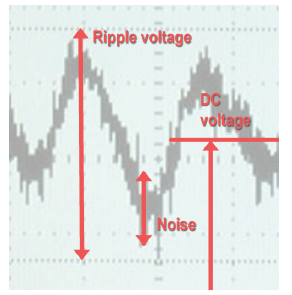
The high frequency switching in buck and boost converters causes high current changes in short time. The presence of the parasitic inductivity and the converter’s output inductivity and capacity results continuous voltage fluctuation. On top of the ideal output DC voltage an additional superimposed AC component is added. Its frequency equals to the switching frequency or one of its harmonics. This is called voltage ripple. The high frequency AC component is in fact the noise generated by the high current change (dI/dt) on the parasite inductance of the driver.
Reducing the output ripple
Analog circuits, like power amplifiers, sensor ICs or the RF section of GPS systems are highly sensitive for quality of power supply. Minimum requirement for the DC/DC converters to place a paralel capacitor for smoothing the ripple voltage resulted by fluctuation of voltage in each cycles of switching. In order to handle the ripple, a low ESR value component has to be used.
Definition of ESR − As all physical components, capacitors as well are constructed of finite resistance materials, ideal capacitor does not exist. When modeling capacitors one can use the replacement circuit shown on the figure:
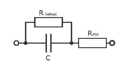
Calculating the electrical behavior of capacitors in circuit design could be done by using the theory of composition of an ideal capacitor element in series with a small resistor, characterizing the so called equivalent series resistance (ESR) and a parallel (high) resistor modeling the leakage or insulating resistance. (Also possible to use a serial inductance, the so called ESL.) The Equivalent Series Resistance or ESR includes the resistance of the dielectric material, the DC resistance of the terminal leads, the DC resistance of the connections to the dielectric and the capacitor plate resistance all measured at a particular frequency and temperature. The RESR component of the electric model in series with the capacitor is the ESR (equivalent series resistance – usually less than 0.1r), and which is temperature dependant. In filtering applications the AC component over the applied DC voltage generates a ripple current flowing through the capacitor.
This current causes an internal temperature rise due to power losses within the capacitor. The ESR defines the capacitor's overall I2R heating losses, which is an important factor especially when used in power and switching circuits.
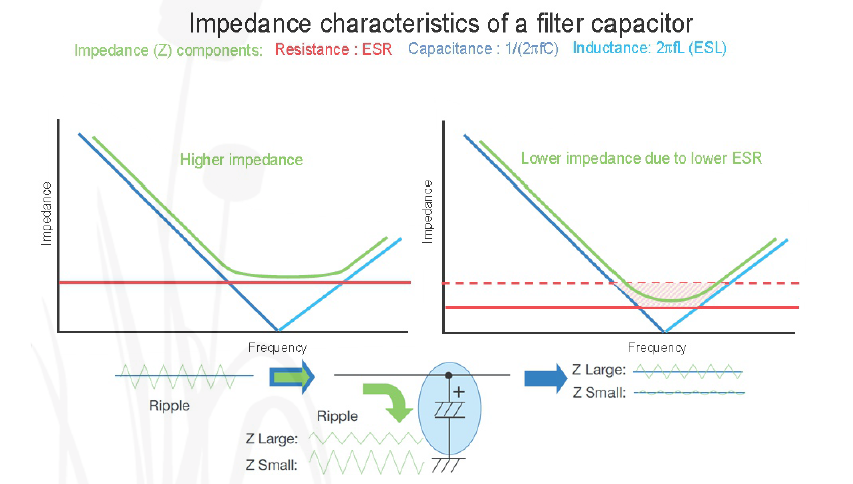
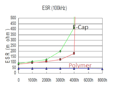
Capacitors with a relatively high ESR have less ability to pass AC current because of their longer charging and discharging RC time constant. As shown on figure, impedance of the capacitor is highly dependent on the ESR value. When the impedance is low, more ripple current can be handled by the capacitor, and the output will be less affected. When the impedance of the filter capacitor is high, remarkable ripple voltage passes through to the output. The ESR of traditional AL E-CAPs increases over time as their liquid electrolyte dries out. Capacitors with very low ESR ratings (polymer, tantalum, ceramic or hybrid) are best suited when using the capacitor as a filter.
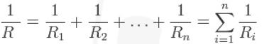
In general ESR can be reduced by using more capacitors of the same type in parallel. The total resistance can be calculated by the figure below :
There are also relative low ESR versions of traditional liquid electrolyte ALECaps, which are cheap, and their rated voltage can be high. Theoretically it is possible to achieve the desired ESR value by using more of them in parallel. In this case we need to accept that the required space can be relatively huge, that is against the today’s trend of miniaturization. The possible evaporation of the liquid electrolyte, the drying out effect makes the ESR non stabile over the lifetime and dependent of operating temperature, therefore it is better to use low ESR capacitors. The cheapest alternative is using multi layer ceramic capacitors, as their ESR is small, they are reliable and available in small sizes.
The disadvantages of the technology are:
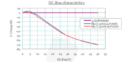
- DC-BIAS: A lot of different capacitors utilizing ceramic dielectrics (MLCC, monolithic, disc) show high decrease of effective capacitance from the nominal capacitance of the capacitor when applied DC voltage approaches the nominal voltage. The problem of DC-BIAS is affecting the class 2 or 3 ferroelectric, non linear dielectrics, such as X7R,X5R, X6S,X7S,X7T,Y5v, while conductive polymer aluminum electrolytic capacitors, conductive polymer tantalum electrolytic capacitors are not affected.
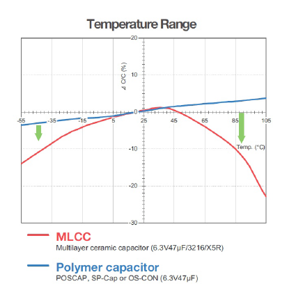
- Their capacitance depends on the ambient temperature.
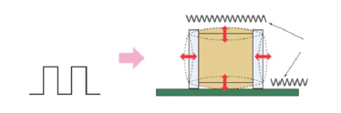
- The ceramic dielectrics show piezoelectric behavior, fast changing of applied voltage generates mechanical vibration, that leads to acoustic noise.
When electronic designs needs a small, reliable, long life solution with high capacitance at high temperatures, solid (e.g. tantalum) capacitors can replace aluminum electrolytic capacitors. In situations where the external environment or dense of component packing results in a sustained hot internal environment and where high reliability is important, equipment such as medical electronics and space – it is a must to use of solid capacitors. When the capacitor is solid (no liquid electrolyte), there is no known wear-out mechanism. Solid-bodied electrolytic capacitors are less subject of drying out than aluminum capacitors, so no decrease in capacitance when used in hot environments or over a long time.
Tantalum capacitors are compact size polarized low voltage devices, having lower energy density and produced to tighter tolerances than aluminum E-caps. The very much porous sintered tantalum grains forming the high surface area anode with a thin oxide dielectric layer, which provides a very high capacitance per unit volume well tolerating hot operating environments up to 125°C. They have lower equivalent series resistance (ESR) than aluminum electrolytic capacitors of the same capacitance, which is a significant advantage in many designs. Compared to Al E-Caps, the tantalum capacitors have very stable capacitance and very low impedance at high frequencies, but they are intolerant for spikes over the nominal voltage and reverse polarity.
If failure mode tends to be a shortcircuit, due to the extremely thin dielectric, there is also a possibility of catastrophic thermal runaway failure. The tantalum oxide layer may have weak points, that would cause breakdown, and the increasing leakage current starts anodization and – in ideal circumstances – starts self-healing the oxide layer. However, if the energy dissipated at the failure point is high enough, the tantalum will act as a fuel and the manganese dioxide of the cathode will oxidize the process and component will burn, which makes them impossible to use e.g. in automotive applications.
Panasonic polymer capacitors
Using polymer materials as high conductivity electrolyte like Panasonics’s POSCAP™ series give even more advantages compared to tantalums using MnO2. It is possible to keep same capacitance with smaller case size providing cost advantages on component density as well as better electronic parameters. With smaller case size, the ESR and ESL values are smaller, making possible to reduce also the number of components being used on the circuit board. (Also possible to achieve higher capacitance on lower rated voltage with the same physical size). Due to the extremely low ESR, POSCAPs have excellent ripple removal ability. The ESR and the impedance is stabile regardless of temperature within wide range of –55 to 1 05 0C. The conductive polymer used in the construction has a self recovery capability, small defects on the insulation layer cause leakage current which will self-heal the insulation, and because of the oxygen free material there are no problems with flammability. PosCaps are normally more expensive than tantalum capacitors, but due to downsizing, it is always possible to make savings if we can use e.g. one piece of capacitor instead of three. A further advantage of the polymer structure that even on the PosCap’s breakdown voltage (2-4 times the rated voltage) no flame appears, which makes a high safety against the MnO2 tantalum capacitor. The main area of using PosCaps could be the smoothing capacitor for DC-DC converters, as the ESR value is extreme low, the ripple current passes easier, therefore the ripple voltage is smaller.
Panasonic’s industry leading SP-Cap™ Polymer Aluminum Capacitors, are surface mount (SMT) capacitors that utilize a conductive polymer as their electrolyte material in a layered aluminum design. SP-Cap™ capacitors are primarily used as input and output capacitors for DC/DC converters due to ultra-low ESR values, high voltage options, and the ability to withstand high reflow temperatures. Panasonic SPCap ™ Polymer Aluminum Capacitors offer capacitance values up to 560`F, voltage values ranging from 2V to 25V, and are free from temperature drift.
Panasonic's product line contains a third type of polymer capacitor family called OS-CON™ Aluminum-Polymer Solid Capacitors. OS-CON Capacitors utilize aluminum and a highly conductive polymer material to offer low ESR, excellent noise reduction and ripple current capabilities. OS-CON parts are characterized by a long life span and minimal changes in ESR throughout the entire rated temperature range.
By using the latest conductive polymer technology even ten times higher conductivity could be achieved compared to organic semiconductor electrolytes, so the ESR value could be ultra low, and does not change even on low temperature, therefore OS-CON capacitor is suitable for outdoor applications. Just like with PosCaps it is also possible to downsize the circuit by using only one piece of OS-CON instead of three pieces of conventional AL ECaps of even bigger size. As the lifetime expectations of conventional E-Caps regards, 1 0 degrees of ambient temperature decreasing results double lifetime. In OS-CON technology, 20 degree of temperature drop will result ten times higher lifetime. We also need to consider that solid electrolyte capacitors are normally have higher leakage currents in order to support the self healing, therefore the maximum rated voltage of these devices is lower than conventional E-caps.
OS-CONS are best used as
- smoothing capacitors in industrial electronics (long life and solution for DC bias problem – capacitance does not change if voltage applied),
- as backup or bypass capacitors for power supplies (quick responding on high speed load change in large current) or
- low-pass filters in consumer products, where excellent noise reduction capabilities provided by low ESR characteristics could be used and other filter elements, like E-caps and inductors could be left out from the design, providing downsizing.
Advantages of polymer capacitors against other technologies
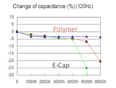
The most important advantage of polymer capacitors in comparison with conventional liquid electrolytic Al Ecaps is, that they are characterized by having stabile (low) ESR, and stabile capacitance over lifetime an in function of temperature.
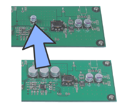
Using polymer technology the designer can save space on the PCB, it is no more needed to use many conventional Al electrolytic capacitors in parallel to achieve the desires low ESR, but enough to use one even smaller e.g. OS-CON:
The polymer capacitors do not loose effective capacitance neither when nominal voltage applied nor as a function of temperature:
Hybrid capacitors
Leading capacitor manufacturers, among others SUN Electronics Industries as well as Panasonic offer special series of hybrid capacitors.
The EP-CAP Capacitors combine the advantages of non-solid Aluminum electrolytic Capacitors (wide voltage and capacitance range, low leakage current, price) with the advantages of solid polymer Capacitors (Low ESR, High Ripple, long life).
As the structure regards, EP-Caps have similar construction that conventional aluminum E-caps, but the electrolyte is combined with conductive polymer material. The liquid electrolyte and polymer molecules are mixed forming a gel substance.
The liquid material
- helps the incomplete oxide layer to repair on lower leakage current (self healing)
- therefore provides higher rated voltage that pure solid capacitors
The polymer material provides better electronics and lifetime properties.
- Extra low ESR values making possible to downsize the circuit, and gives excellent noise absorption capability on high frequencies
- High ripple current ability makes it possible to use these components in smoothing circuits of switching regulators
- The performance is stable even in low temperature, and over wide range of operation temperatures
- No need of voltage derating, applying voltage till the rated voltage is guaranteed.
Summary:
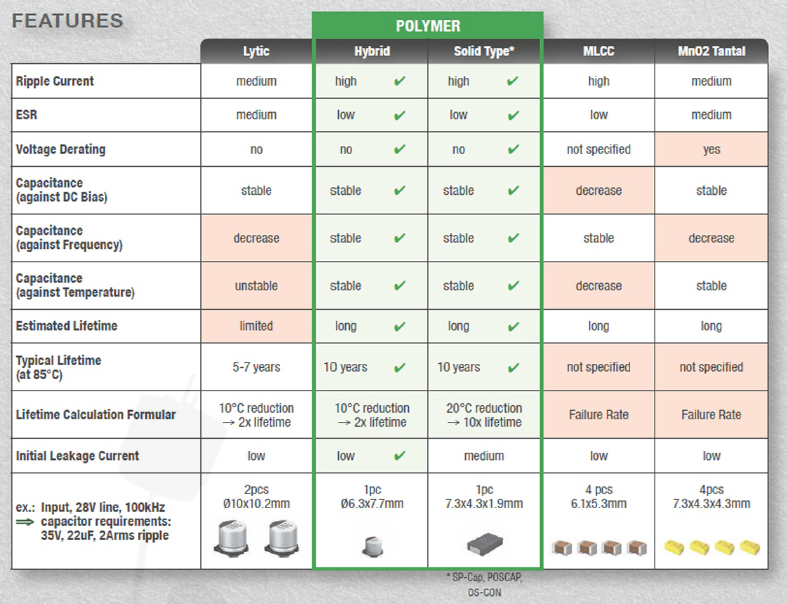
Capacitors with polymer and hybrid electrolyte provide good ripple handling capabilities and are successfully applicable instead of conventional electrolytic capacitors as output filters in DC/DC converters. The low ESR makes it possible to use few of the capacitors of a smaller type rather than many of parallel connected bigger conventional E-caps resulting smaller PCB size. Due to their stabile ESR and capacitance values over lifetime and temperature, having no voltage derating and acoustics noise make them also suitable alternatives for MLCCs.

| Share on Facebook | Share on LinkedIn |
References
This article has been published on the following locations:
| # | Media | Link |
|---|---|---|
| 1 | Elektronet 2015/8 | Elektronet : elektronikai informatikai szakfolyóirat, 2015. (24. évf.) 8. sz. 20-23. old. |
| 2 | Elektronet online | DC-DC átalakítók kimeneti feszültség-hullámosságának csökkentése |
| 3 | Hungarian version | Feszültséghullámosság csökkentése polimer kondenzátor használatával |
| 4 | TechStory M2M | DC-DC átalakító kimeneti feszültséghullámosságának csökkentése |