


Zoltán Kiss- Area Sales Manager - East Europe - Endrich GmbH.
Ceramic heat sinks for cooling of LEDs & semiconductors drivers – ABC Taiwan
9 February 2015

Summary :
Electric components, such as LEDs or semiconductor elements of their drivers generate heat, and their lifetime, reliability and efficiency highly depend on the adequate cooling, which should remove and dissipate the heat as fast as possible. As the efficiency is a key factor, it is not possible to use active cooling, but heat sinks. Metal heat sinks have a number of disadvantages in comparison to microporous ceramic heat sinks, like their weight, higher thermal capacity and lower active surface. Ceramic incorporates two crucial characteristics of heat sinks, electrical insulation and energy disperse ability. It possesses good electromagnetic compatibility and in addition it is UV and corrosion resistant. This paper shows facts through the products of ABC Taiwan Electronics.
The heat generated by the electronic components must be quickly dissipated, as remaining inside the enclosure the reliability and efficiency will decrease significantly. There are passive and active solutions for external cooling. Active cooling involves extra substance (e.g. gas or liquid) to remove heat from the component by using extra energy to keep this coolant moving, like air flow of fans or fluid, which flows around the component. When it is not economical to invest extra energy for this purpose, such as in LED lighting systems, the preferred way of cooling is to use a heat sink that has a material having good heat conductivity and has enough effective surface in contact with the surrounding cooling medium, such as the air. Metal heat sinks are widely used by the industry, but the ideal material would provide electrical insulation while ensuring adequate heat conductivity, that can be realized by using multiple layers of different materials. Each layer is an extra production cost factor as well as potential risk of delamination, corrosion and degradation due to the different thermal coefficients. These layers also pose an additional obstacle to thermal conductivity.
Thermal characteristics of LED systems
Power dissipated by the junction of the LED chip acts like a constant current heat generator, which raises the critical Tj (junction) temperature inside the enclosure of the LED above the ambient temperature (Tamb). The heat energy itself can be considered as an equivalent of electrical current and the temperature rise as the equivalent of electrical voltage drop.
To construct the corresponding thermal “Ohm’s Law we should consider the physical phenomenon of thermal resistance as a property of materials, that acts like the electrical resistance, the more heat energy flowing through on it, the higher the temperature rise will be:
Tj-a=Pd * Rth(j-a)
Where,
Pd: is the dissipated power [W]
Tj-a: is the temperature rise of the junction above the ambient temperature [°C]
Rth(j-a): is the total thermal resistance between junction of the LED and the surrounding ambient [°C/W]
When designer wants to keep the temperature rise of the LED junction controlled within specification at a certain power rate, the only way to reduce it is to lower the total thermal resistance, which is constructed as a composition of the thermal resistance of junction to case (Rth(j-c)), the case to PCB substrate, the PCB to insulator, the insulator to heat sink.
We cannot influence the Rth(j-c), anyway this is rather small in comparison with the other thermal resistance of the total path, but we can do something with the Rth(c-a) which is the task of the heat sink. The heat will be dissipated primarily by conduction and convection and to a lesser extent by radiation. The heat sink should have low thermal resistance to support conduction, improved surface to assist both radiation and air convection. Of course minimize the negative affect of tiny trapped air caused gaps between the case and the heat sink, or the mica or plastic electrical insulators, it is mandatory to use a low thermal resistance heat compound paste. This will provide the best thermal joints, but the main way to minimize the total Rth(j-a) is to enhance the heat sink itself.
Ceramic heat sinks
Today the material technology of ceramics makes it possible to use microporous ceramic heat sink that is lighter, dissipates heat faster than metal ones, without storing heat within itself. A ceramic heat sink having a micropores structure provides a huge effective surface, so that the heat dissipation capacity of the ceramic heat sink is greatly enhanced.
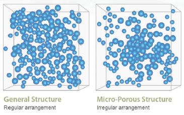
MPC (micro porous ceramics) structure provides very large surface area to contact air and has excellent property of heat radiation and heat convection. This is the key factor of the heat sinking. The surface area of MPC is 30% greater than the metal has. Hence, MPC has more surface area to contact air, the convection medium. MPC can dissipate more heat in a unit time.
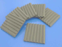
In comparison with the fin-type of metal heat sinks ABC’s ceramic heat sink is smaller, lighter while it has better heat dissipation in the same time.
| Density (g/cc) | Thermal conductivity (W/m-k) | Thermal capacity (J/g-°C) | |
|---|---|---|---|
| Cu | 8.96 | 385 | 0.385 |
| Al | 2.7 | 210 | 0.9 |
| MPC | 3.1 | 125 | 0.67 |
The above chart shows copper to be the material with lowest thermal capacity.
| Volume (cm3) | Weight (g) | Thermal capacity of Unit volume | |
|---|---|---|---|
| Cu | 1 | 8.96 | 3.45 |
| Al | 1 | 2.6 | 2.43 |
| MPC | 1 | 3.1 | 2.08 |
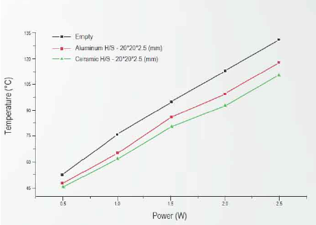
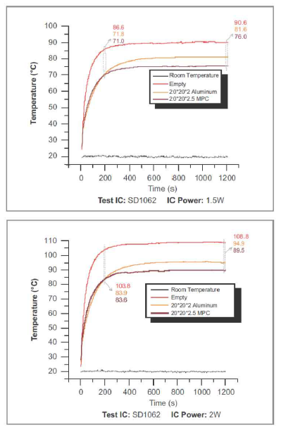
But if we look at the thermal capacity in terms of unit volume, copper has the highest value, higher than that of aluminum and MPC. This means, when same physical size of copper and aluminum blocks heat up, they store the heat longer. MPC has the lowest thermal capacity for the same volume, therefore dissipates heat faster than metal heat sink without storing heat within itself. Ifwe look at the test results of cooling an IC with AL, Cu and MPC heat sinks, we can see that the temperature of the heat sink is he lowest in case of using MPC material.
We have to also mention however, that the heat conductivity of the MPC material (1 25 W/mK) is lower than the Al (21 0W/mK) or Cu (385mK) material. This means that in case of cooling high power circuit elements, such as power LEDs of 5W and higher, the MPC based cooling solution might be not as efficient as with fin-type metal heat sinks, as in this power area the heat conductivity has higher importance. At lower power the advantage of the extremely higher thermal disperse surface area makes the heat sinking ability of MPC material much better, than the traditional metal ones of the same size. With simple words MPC is perfect to dissipate heat to air, rather than conduct heat away from source. A combination of a thin metal conductive block and a ceramic heat sink can be an ideal solution for replacing an expensive and large volume fin-type metal heat sink.
As the ceramic material is electrically non conductive (insulation up to AC 5,000 Volts), there will be no antenna effect in the circuit, reducing EMI/EMC issues.Due to the porous structure higher radiation surface could be realized, while the physical size is much smaller than the fin type of metal heat sink, therefore remarkable downsizing, weight and cost reduction can be achieved. Light and thin design can be realized in a huge variety of shapes, thickness can be as less as 2mm. Costs are lower as it has a simple production process, has material of a lower price, and has lower costs of fabrication. The heat sink made of foamed aluminum and the heat sink made of the micropores ceramic are compared as follows: In the heat sink made of foamed aluminum, the heat dissipation capacity is 5W/cm2, and the equivalent convection thermal conduction coefficient is 0.5W/cm2°C. In the heat sink made of the micro-pores ceramic, the heat dissipation capacity is 229.1W/cm2, and the equivalent convection thermal conduction coefficient is 12.06W/cm2°C. Thus, the heat sink made of the micropores ceramic is better than the heat sink made of foamed aluminum.
| Share on Facebook | Share on LinkedIn |
References
This article has been published on the following locations:
| # | Media | Link |
|---|---|---|
| 1 | Elektronet 2015/1 | Elektronet : elektronikai informatikai szakfolyóirat, 2015. (24. évf.) 1. sz. 20-21. old. |
| 2 | Elektronet online | Kerámia hűtőbordák LED és LED driver félvezetők hűtésére |
| 3 | Hungarian version | Kerámia hűtőbordák LED és LED driver félvezetők hűtésére - ABC Taiwan |