


Zoltán Kiss- Area Sales Manager - East Europe - Endrich GmbH.
Electrolytic capacitor essentials
05 October 2012

Summary :
Aluminium Electrolytic Capacitors are essential elements for almost all electronic circuits. The constant growth of using electronics in every day life has driven the usage of these components. In most of the applications the lifetime of the electronic device is closely linked to the lifetime of the E-caps inside. In order to provide reliable operation for the electric circuit over a definitive period, a clear knowledge of the properties of the capacitors is mandatory. In this article we try to give an overview of the main features of the capacitors, the lifetime issues and will introduce special capacitor families with special properties and other non-wet electrolyte solutions from SUN Electronics Industries and Sanyo.
Capacitors in general
Capacitors are electronic components conduct alternating current (AC) and block DC current. They are able to couple circuit blocks allowing AC signals to be transferred while blocking DC power, to store energy, and to filter signals according to their frequency. Capacitors can store electric charge for a time indefinite on conductive plates, separated by a non conductive dielectric layer. As the charge grows, the electric field through the dielectric also increases making the voltage between the electrodes rising proportionally. The ratio of the charge magnitude to the electric potential (voltage) between the plates is defined as capacitance, which – together with the maximum applicable voltage – characterize the capacitor. The capacitance of a component depends on the plate geometry and the properties of the applied dielectric. When the charge as well as the voltage of the capacitor increases, there will be a certain point when the dielectric material will no longer be able to insulate the charges of the plates from each other, and dielectric breakdown occurs, charge will be lost and internal heat is generated. This happens at the breakdown voltage, so the working voltage of the capacitor must be defined below this voltage level.
In order to describe the performance issues of electrolytic capacitors, we need to review the electrical properties of the components.
Circuit model - Equivalent series resistance (ESR), leakage current, ripple current
All physical devices – so capacitors as well- are constructed of materials with finite electrical resistance, and cannot be just supposed to have pure capacitance. Therefore calculating the electrical behavior of capacitors in circuit design could be done by using the theory of composition of an ideal element in series with a small resistor , the so called equivalent series resistance (ESR) and a parallel (high) resistance the leakage or insulating reisistance.
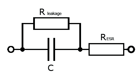
The dielectric material inside the capacitor - being a non-perfect insulator - causes a very small leakage current flowing through the dielectric due to the electric field built up by the charge on the plates. This small DC current of the nano-amps (nA) region is called the capacitors Leakage Current. Leakage current is in fact the movement of electrons through the dielectric medium, around its edges, which will be discharging the capacitor after a while whan the supply voltage is removed. In the equivalent model the leakage is represented by a leakage resistance in parallel with the capacitor as shown on the figure. This resistance is often called insulation resistance, when the value is very high – especially in foil capacitors. When the leakage current is high as in electrolytic capacitors it is usually called leakage resistance. Capacitor leakage current is an important parameter, the higher the leakage current the lower the storage capability of the capacitor is. The Equivalent Series Resistance or ESR, of a capacitor is the AC impedance of the capacitor when used at high frequencies and includes the resistance of the dielectric material, the DC resistance of the terminal leads, the DC resistance of the connections to the dielectric and the capacitor plate resistance all measured at a particular frequency and temperature. The RESR component of the electric model in series with the capacitor is the ESR (equivalent series resistance –usually less than 0.1Ω), and which is frequency (and temperature) dependant. In most applications there is an AC component over the applied DC voltage, which generates a so called ripple current defined as the rms value of alternating current flowing through the capacitor. This current causes an internal temperature rise due to power losses within the capacitor. The ESR defines the capacitor's overall I2R heating losses, which is an important factor especially when used in power and switching circuits. Capacitors with a relatively high ESR have less ability to pass current to the external circuit because of their longer charging and discharging RC time constant. The ESR of (wet) electrolytic capacitors increases over time as their electrolyte dries out. Capacitors with very low ESR ratings are available and are best suited when using the capacitor as a filter.
Lifetime issues of E-caps with liquid electrolytes
The liquid electrolyte inside the capacitor is the main reason of its finite lifetime and the continuous change of the electrical parameters. The flow of current through the wet electrolyte is mediated by ionic movements, and when the temperature rises the viscosity of the liquid decreases, causing lower ESR therefore higher ripple current. The material boiling point of the electrolyte determines the maximum ripple current causing self heating added to the ambient temperature. The electrochemical reactions inside the electrolyte and the drying out lead to a drift of electrical parameters and result a finite lifetime. Generally accepted lifetime model applicable to electrolytic capacitors takes three factors in consideration when calculating expected lifetime:
- The temperature factor counts with the rule derived from the Arrhenius equation, an ambient temperature drop by 10 K doubles the lifetime
- The impact of the applied ripple current, which causing self heating
- For bigger size E-caps, the applied voltage gains impact on the lifetime, because the operating voltage below the nominal voltage causes less stress to the dielectric layer. Approaching the rated voltage with the applied voltage, more electrolyte is consumed for the self-healing, which is also exponentially depending on temperature.
The formula, which could be used for lifetime expectations of E-caps could be used as shown below:
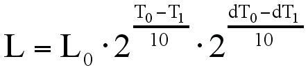
L: Expected life (hrs) at temperature T1 °C
L0: Guaranteed life (hrs) at temperature T0 °C
T0: Maximum operating temperature (°C)
T1: Actual operating temperature (°C)
dT0: Temperature rise due to rated ripple current caused self heating (°C)
(For Suncon radial leaded capacitors of 85 °C dT0 = 5 °C, for 105 °C types is 3-4 °C, for SMD types ,1.5-3 °C)
dT1: Temperature rise due to actual ripple current caused self heating (°C)
Taking the impact of the different ripple current in account:
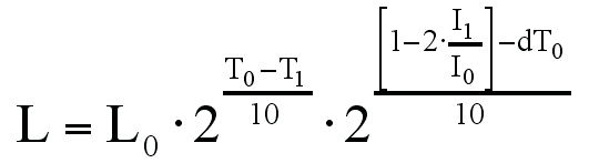
I0 : Rated ripple current (ARMS)
I1 : Actual ripple current (ARMS)
Aluminum electrolytic capacitors
Aluminum electrolytic capacitors are constructed from two conducting aluminum foils, one of them is coated with an insulating (dielectric Al oxide) layer, and a paper spacer soaked in electrolyte. The foil with the insulated layer is the anode while the liquid electrolyte and the second foil acts as the cathode. The so called electrolyte is a non-metallic conductive substance, an ionic conducting liquid to achieve a larger capacitance per unit volume than other types, but with performance disadvantages.
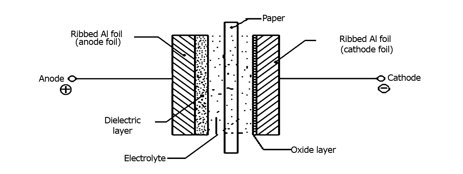
This layered construction is then rolled up, fitted with pin connectors and placed in a cylindrical aluminum casing. The two most popular geometries are axial leads coming from the center of each circular face of the cylinder, or two radial leads or lugs on one of the circular faces.
The dielectric oxide layer is maintained by an electrolytic process, the foil is surrounded by liquid and current is passing through the liquid into the metal, forming the oxide layer. The advantage is, that the dielectric layer has self-healing capabilities, whenever DC voltage is applied to the capacitor, if a weak point occurs, the resulting leakage current drives a so called anodization (formation) process, which grows the dielectric to the thickness, which is required to support the voltage and rebuild the isolation. So better to charge the E-caps continuously and keep them under mild use.
The disadvantage however is that if reversing the polarity, even the slightest leakage will begin to tear the dielectric down, resulting in more leakage, which is a self amplifying process resulting breakdown of the component. Most of electrolytic capacitors are polarized types, so the voltage connected to the capacitor terminals must have the correct polarity. Incorrect polarization can cause the oxide layer inside the capacitor to break down resulting in very large currents flowing through the device resulting in destruction.
Another problem is the presence of the electrolyte itself, possible drying out by evaporating the liquid, building up pressure, which may result in a leak, even an explosion. When leakage occurs and electrolyte escapes, it will interact corrosively with other parts of the circuit. The construction gives a limited life-span, after a while, the dielectric may deteriorate beyond regeneration, resulting in a high leakage current, or the electrolyte will eventually dry away, reducing the capacity drastically.
Electrolytic-type capacitors may have very high capacitances, but they also have very high leakage currents (typically about 5-20 μA per µF) due to their poor isolation/leakage resistance, and are therefore not suited for storage applications. Also, the flow of leakage current for aluminium E-caps increases with temperature. The advantages of E-caps are the high capacitance per unit and the ideal cost structure. SUN Electronics Industries offers a number of series of Al E-caps, with special properties like reduced ESR, long lifetime and high temperature versions next to the cheap, standard versions.
Solid (polymer) capacitors
Tantalum versus Sanyo PosCap
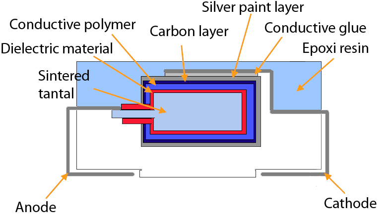
When electronic designs needs a small, reliable, long life solution with high capacitance at high temperatures, solid (e.g. tantalum) capacitors can replace aluminum electrolytic capacitors. In situations where the external environment or dense of component packing results in a sustained hot internal environment and where high reliability is important, equipment such as medical electronics and space - it is a must to use of solid capacitors. When the capacitor is solid (no liquid electrolyte), there is no known wear-out mechanism. Solid-bodied electrolytic capacitors are less subject of drying out than aluminum capacitors, so no decrease in capacitance when used in hot environments or over a long time.
Tantalum capacitors are compact size polarized low voltage devices, having lower energy density and produced to tighter tolerances than aluminum E-caps. The very much porous sintered tantalum grains forming the high surface area anode with a thin oxide dielectric layer, which provides a very high capacitance per unit volume.
Tantalum capacitors have very low electrical leakage current, so will hold the charge for a long time, and tolerate hot operating environments up to 125 °C. They have lower equivalent series resistance (ESR) than aluminum electrolytic capacitors of the same capacitance, which is a significant advantage in many designs. Compared to Al E-Caps, the tantalum capacitors have very stable capacitance, little DC leakage and very low impedance at high frequencies, but they are intolerant for spikes over the nominal voltage and reverse polarity. If failure mode tends to be a short-circuit, due to the extremely thin dielectric, there is also a possibility of catastrophic thermal runaway failure. The tantalum oxide layer may have weak points, that would cause breakdown, and the increasing leakage current starts anodization and - in ideal circumstances – starts self-healing the oxide layer. However, if the energy dissipated at the failure point is high enough, the tantalum will act as a fuel and the manganese dioxide of the cathode will oxidize the process and component will burn, which makes them impossible to use e.g. in automotive applications. They are more expensive than wet aluminum electrolytic caps, but because of advantages, and compact sizes, they could be used in miniature applications like cellular phones.
Using polymer materials as high conductivity electrolyte like SANYO’s POSCAP series give even more advantages compared to tantalums using MnO2. It is possible to keep same capacitance with smaller case size providing cost advantages on component density as well as better electronic parameters. With smaller case size, the ESR and ESL values are smaller, making possible to reduce also the number of components being used on the circuit board. (Also possible to achieve higher capacitance on lower rated voltage with the same physical size). Due to the extremely low ESR, PosCaps have excellent ripple removal ability. The ESR and the impedance is stabile regardless of temperature within wide range of –55 to 105 °C. The conductive polymer used in the construction has a self recovery capability, small defects on the insulation layer cause leakage current which will self-heal the insulation, and because of the oxygen free material there are no problems with flammability.
PosCaps are normally more expensive than tantalum capacitors, but due to downsizing, it is always possible to make savings if we can use e.g. one piece of capacitor instead of three. A further advantage of the polymer structure that even on the PosCap’s breakdown voltage (2-4 times the rated voltage) no flame appears, which makes a high safety against the MnO2 tantalum capacitor. The main area of using PosCaps could be the smoothing capacitor for DC-DC converters, as the ESR value is extreme low, the ripple current passes easier, therefore the ripple voltage is smaller.
Solid Aluminum Electrolytic capacitor with organic semiconductor electrolyte (OS-CON)
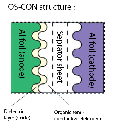
SANYO also invented a new generation of E-cap in which the aluminum foil layers are encapsulated into a solid semiconductive material instead of liquid electrolyte. The material is thermoformed to final shape which enhances its conductivity and helps protecting the capacitor from excess heat surges. Comparing the OS-CON structure with the aluminum E-Cap structure the biggest difference is the material of the electrolyte itself. This organic semiconductive material has the conductivity almost hundred times higher than conventional E-Caps and even ten times higher than solid electrolyte capacitors with manganese dioxide. By using the latest conductive polymer technology even ten times higher conductivity could be achieved compared to organic semiconductor electrolytes, so the ESR value could be ultra low, and does not change even on low temperature, therefore is suitable for outdoor applications. Just like with PosCAps it is also possible to downsize the circuit by using only one piece of OS-CON instead of three pieces of conventional AL E-Caps of even bigger size. As we had an overview of the lifetime expectations of E-Caps, we have seen that 10 degree of ambient temperature decreasing will result double lifetime. In OS-CON technology, 20 degree of temperature drop will result ten times higher lifetime.
We also need to consider that solid electrolyte capacitors are normally have higher leakage currents in order to support the self healing, therefore the maximum rated voltage of these devices is lower than conventional E-caps.
OS-CONS are best used as
- smoothing capacitors in industrial electronics (long life and solution for DC bias problem – capacitance does not change if voltage applied),
- as backup or bypass capacitors for power supplies (quick responding on high speed load change in large current) or
- low-pass filters in consumer products, where excellent noise reduction capabilities provided by low ESR characteristics could be used and other filter elements, like E-caps and inductors could be left out from the design, providing downsizing.
Hybrid capacitors
SUN Electronics Industries offers special series of hybrid capacitors. The EP-CAP Capacitors combine the advantages of non-solid Aluminum electrolytic Capacitors (wide voltage and capacitance range, low leakage current, price) with the advantages of solid polymer Capacitors (Low ESR, High Ripple, long life). As the structure regards, EP-Caps have similar construction that conventional aluminum E-caps, but the electrolyte is combined with conductive polymer material, therefore non liquid but gel substance.
The liquid electrolyte and polymer molecules are mixed.
The liquid material
- helps the incomplete oxide layer to repair (self healing),
- provides higher rated voltage that pure solid capacitors
The polymer material provides better electronics and lifetime properties.
- Extra low ESR values making possible to downsize the circuit, and gives excellent noise absorption capability on high frequencies
- High ripple current ability makes it possible to use these components in smoothing circuits of switching regulators
- The performance is stable even in low temperature, and over wide range of operation temperatures
- No need of voltage derating, applying voltage till the rated voltage is guaranteed.
| Manufacturer | Cap. range | Voltage range | Lifetime | ESR | Temp. range | Linearity | Leakage-current | Comment | |
|---|---|---|---|---|---|---|---|---|---|
| Al E-Cap | SUNCON | Up to 6800uF | Up to 400V | -10 oC 2X longer | Quite high for standard | Up to 125°C (new serie 135°C) | Non linear over f and T | Low | Automotive approved TS 16949 and AECQ200 |
| OS-Con | PANASONIC | Up to 1500 uF | Up to 35V | -20 oC 10X longer | Ultra low | Up to 125°C | Linear and stable over f and T | High | |
| PosCap | PANASONIC | Up to 2700 uF | Up to 35V | -20 oC 10X longer | Ultra low | Up to 125°C | Linear and stable over f and T | High | Non flammable |
| EP-CAP | SUNCON | Up to 560 uF (6V Typ HVA 10x10,5 even 1000uF) | Up to 125V | Long lifeime | Low | Up to 135°C | Linear and stable over f and T | Low | Automotive approved TS 16949 and AECQ200 |
Samples, datasheets and engineering support could be requested by the author.
| Share on Facebook | Share on LinkedIn |
References
This article has been published on the following locations:
| # | Media | Link |
|---|---|---|
| 1 | Elektronet 2012/5 | Elektronet : elektronikai informatikai szakfolyóirat, 2012. (21. évf) 5. sz. 28-29. old., 6. sz. 24-25. old. |
| 2 | Elektronet online | Elektrolitkondenzátorok |
| 3 | Hungarian version | Elektrolitkondenzátorok |