


Claudius Klose – senior product manager of electromechanics components, Zoltán Kiss - export manager - Endrich Bauelemente Vertriebs GmbH.
Design of system cooling using DC axial fans
13 February 2019

Summary :
Cooling has a key role in today’s electronics, as the lifetime expectancy of passive and active components is highly dependent on the way of transferring the heat generated by their electric current towards the surrounding environment. In some cases the properly designed PCB and using a heatsink provides adequate surface to remove the heat emitted by the components, in other cases the system needs active cooling e.g. by forced flow of air. The design of cooling is often not part of the functional design of the electronic devices, however this has to guarantee the reliable primer functionality. Usually a fan used without proper selection may result in oversized mechanical measures, or - in worst case - undersized cooling efficiency. Today’s miniaturization trends make not possible to unnecessarily enlarge enclosure size, while the competition does not allow produce unreliable products. Therefore cooling design cannot be started early enough, just like without proper circuit protection, no electronics device can provide its primer functionality for long time without sufficient cooling. Our article is about some important selection criteria of the proper fan depending on the application conditions.
When the heat of a device should be removed, the heat is transferred on one of the three ways:
- The heat may leave through thermal conduction, when the heat source is in direct contact with another heat conductive material such as the PCB, heatsink or chassis
- Through radiation, when the generated heat is directly transferred to the environment as an electromagnetic wave.
- Through convection, when the heat is released by the flow of warming particles of the surrounding medium to the atmosphere.
The last way acts the most important role in active cooling of electronics systems. Convection may be natural, when the flow is generated by temperature difference, or forced, when the stream is created by external force such as the rotation of an impeller. Forced convection is extremely effective towards the cooling of electrician devices, either provided by high volume airflow of axial fans or high pressure air of radial blowers. The most important design aspect is to leave sufficient space for this flow around the most heat-critical parts concerned, the fan and its power supply, paying special attention at least of the proper air-intake and exhaust vents. If these criteria are taken in consideration during functional design, an important step is taken into the direction of reaching the maximum performance of the application and to avoid later stage compromises between functionality and sufficient cooling.
When using forced convection the most of the heat generated by the components leave the system on the following way:
- Heat generated on the component
- Heat convection from component to surrounding air particles inside the chassis
- Discharge heat with the airflow
(2) may be supported by providing large surface area on the component or increasing the volume of air flow. In former case we have a choice to use a larger component or attach a heatsink, in latter case either reduce component density, using larger air-intake or using more fan or higher speed could be solution. When applying active air cooling it is possible to suck warm air out of the chassis or blow in cold air to the components. Although in these solutions nearly the same volume of airflow can be used for cooling, both arrangements have their own advantages and disadvantages. Air drawn into the fan flows laminarly providing uniformly distributed particle velocity in the chassis, therefore no hotspots and stagnant air are present. The air exhausted by the fan becomes turbulent, which offers twice as better heat dissipation than in laminar flow with the same volumetric flow rate. But this turbulent zone is concentrated near the exhaust of the fan and due to possible recirculation a huge loss in airflow may happen inside the chassis if the air velocity profile is not well defined and the air flow path is not developed by using huge vents and air bafflers. During design it is advisable to use the natural convection as well, warm components should be placed above cool ones, huge components should not block the airflow from small ones.


The exhaust fan sucks the warm air out of the chassis, which reduces the air pressure of the enclosure, causing dust drawn into the housing with the air going in through of the vents and holes. This may be accumulated and deposited on the components causing reduced convection and prevents effective cooling. If exclusion of dust is required, it is better to use a fan pushing cold air into the chassis, where an inlet filter may offer good protection against dust. As in this arrangement there will be slightly higher pressure inside the enclosure, which prevents airborne dust to penetrate through holes and vents. The filters should be replaced time to time to avoid dust accumulation, which may prevent airflow, therefore causing even bigger problem than the dust would create inside the enclosure. The other advantage of this arrangement is that the room temperature air does not stress the bearings as much as the warm air at exhaust types of fans, which results in 2-3 times higher lifetime. Some small drawback is caused by the own heat dissipation of the fan motor, which slowly warms up the incoming air and therefore reducing the cooling efficiency. For the same reason it is the best to place the most heat critical components near the inlet and the highest temperature ones near the outlets. Before going deeper in required air flow calculations, it is very important to decide about the geometry of the used fan. When requiring high volumetric airflow, it is advised to use an axial fan, in case we have to overcome a high static pressure a radial blower can be used. As this article is about axial DC fans, we do not detail the selection of radial blowers, in case it is necessary to increase the pressure, we choose other methods such as e.g. using multiply axial fans in serial arrangement. Although the proper fan selection depends on many factors, at first stage in designing a forced air cooling system is to determine the required air flow volume. This is primarily defined by the total heat generation of the system, and the allowed maximum temperature rise.
In order to calculate the required airflow Q [m3/min] we need to obtain the following values:
- The power dissipated within the system (worst-case estimation) : Ploss[W]
- The k constant describing the packing density of the components that prevent the free flow of air (k=80-95 rare placement, k=60 dense components)
- The maximum allowed temperature rise that is defined by the operating temperature range of the used components (∆T)
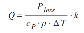
Where,
Q: required airflow [m3/min]
cp: heat capacity of the air at constant air pressure: 1007 J/(kgK)
ρ: air density: 1.2 kg/m3 @ 25 °C
Taking the usual experimental values of the constants in consideration the formula of the required airflow may be simplified like this:
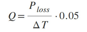
[m3/min]
In practice this means that a system dissipating 200W requires 0.5 m3 airflow a minute to keep at maximum 20 °C of temperature rise. Although this theoretical calculation provides exact volumetric airflow requirement, it does not give adequate answer for the practical problem, whether the selected fan will provide this airflow or not, since it does not hold enough information about the interaction between the fan and the system to be cooled. It is much more complicated to calculate how does a certain cooling fan act in a specific system arrangement. To step forward we need to know the non-linear relationship between the fan’s volumetric air flow and its static pressure represented by the characteristics on figure 3. The static pressure is maximized when the airflow path is completely obstructed, at this point the volumetric airflow is zero (intersection with Y axis). The maximum possible airflow can be read out at the intersection of the characteristics with axis X, which point represents the case no obstructions at all, free flow of air is enabled. (see fig. 6)

The characteristics describing the real cooled system’s obstruction against the airflow is called the system impedance curve (SIC). The system impedance curve describes the static pressure rise over the airflow and can be described by a nearly quadratic equation: Ps ~ Q1.75… 2
It can be generated experimentally by applying various air flow rates to the system and measuring the enclosure pressure it generates.

In forced convection cooled systems, the above two characteristics play important role. The point of intersection of the fan’s air performance (P-Q) curve and the system impedance curve will define the operating point of the cooling solution.


We can see some remarkable operating points on fig 6. In case of blocked enclosure, the static pressure grows to the maximum value and the airflow is completely blocked. When there are no obstacles in the air flow path, the theoretical value of static pressure is zero, the volumetric air flow is at maximum. The two usual operating point represents a dense packed system and a normal system. In the first case the high system impedance could be only compensated by applying higher pressure, resulting in lower air flow volume. In the other case as the static pressure is lower, higher volumetric airflow is possible, therefore more effective cooling could be done. In both cases we used the same fan, the operating points have been defined by the different system resistances. Knowing above fact it is now possible to select the proper fan. Nowadays DC fans are more popular than AC versions as their power consumption is usually lower, lifetime is longer, and because their angular speed is proportional to their supply voltage, it is easy to apply speed control. The lower the speed the more silent the operation is, the lower the power consumption and the higher the lifetime will be (due to reduced wear out of the bearing). DC fans produce less EMI than AC versions, there are no geographical issues of supply voltages and frequencies, and price differences already disappeared. Therefore, we only write about DC axial fans in this paper.

After calculating the required air flow rate, having the system impedance curve on hand, we define the static pressure interval, that should be overcome by the fan in order to provide the required air volume. Then using the fan manufacturers’ catalogues a specific device can be selected, that is able to provide the adequate airflow on the level of back pressure required by the SIC. It is advised to select the operating point out of the critical area marked by red on fig 7. This area is the so-called stall area, where the air flow stalls at the blade profile, which makes negative effects. Such an immediate disadvantage is the considerable increase in noise. For longer term negative effect is the vibration, which can reduce functionality and leads to lifetime issues. Therefore, fan should always be operated in the optimum operating area marked with green on fig.7. Further reducing noise at even the optimum operating area can be also important selection criteria, it is advised to select the fan with the highest possible diameter. Bigger sizes mean lower speed, therefore less bearing noise. This is however against today’s miniaturization trends, we should use small, thin fans wherever and whenever possible. If the desired operating area cannot be reached by a single small fan it is possible to use multiple fans next to or behind each other. This arrangement will negatively influence noise and mathematical lifetime expectancy, but offers redundancy, which supports system reliability. It is important to consider size at the beginning, this is not only the question of design and technology trend but on long term influences price of the end product. In the next part of this article series we will describe how to change the operating point by using multiply fans, what are the changed P-Q curves like, how to achieve more airflow or higher pressure. We will also review the methods of fan speed control.
Used literature:
- Claudius Klose –Endrich Bauelemente Vertriebs GmbH. – „ Proper fan selection”
- NMB-MAT fan catalogue – „Fan engineering”
| Share on Facebook | Share on LinkedIn |
References
This article has been published on the following locations:
| # | Media | Link |
|---|---|---|
| 1 | Elektronet 2019/1 | Elektronet : elektronikai informatikai szakfolyóirat 2019. (28. évf) 1. sz. 20-23.o. |
| 2 | Elektronet online | Rendszerhűtés méretezésének kérdései axiális DC hűtőventilátorok alkalmazásakor |
| 3 | Hungarian version | Rendszerhűtés méretezésének kérdései axiális DC hűtőventilátorok alkalmazásakor |
| 4 | South-East European Industrial Market 2019/2 | Design of system cooling using DC axial fans - Part I |
| 5 | Engineerlive | Design of system cooling using DC axial fans |